Friday, December 17, 2010

Input DIrector - Multiples computer from just one interface

I was looking for a tool that allow me to control multiple computer from just one key/mouse.
I know, for long time external key/mouse/display swicthers; they are very nice, but I really want a software to do the job, possible over TCP/IP that control the direction of input data between several computer.
I was almost sure that will find some already done ver internet.
And I found! 2 options! InputDirector and Synergy.
I install and right now testing the InputDirector.
And really works nice!
If you have multiple computers, like notebooks and desktops, and don't like to have to change between keyboards and mouses, this is a really nice software.
It is very light running, and use very few machine resources()compared to several simple comercial softwares like MSN)
Take a look at: http://www.inputdirector.com/index.html and enjoy!

Thursday, October 14, 2010

Debounce Machine! A state approach.

UPDATES IN RED at: 12-11-2010

Reading HackaDay, just can't let to present my debounce routine.
Make my interpretation of it at 2007 with PIC programming.
I start build my debounce routine with a state machine approach.
This way the routine can be solid as stone.(I think least)
And was much more easier to accomplish the right behavior that I wait for.
More, my implementation doesn't force delays, is pretty simple and straight-out - use few bytes of program.
Many keys can be debounced with minimum amount of memory.
Just one byte per key; or less; even a nibble can be used.
And can be combined on a already existent code and interrupt routine.
As I saw on other sites ahead hackaday, it is a low pass filter too.

Below the schematic of all thing.

Created with DiaPortable.

This state machine can be implemented in various ways.
The actual implementation work checking and changing the state on every interrupt (if need).
I prefer compass everything at 5ms interrupt at my routines (due the use I am making).
However if you use a more fast interrupt routine, don't worry, since you may DEFINE the HIGH boundary with a bigger number.
With 4 states (above machine), and 5ms INTs, it can debounce a key in 20ms.
This debounce can be easily converted into code using (I use this way, you are free to chose whatever you want):

  • a variable to register the state of each key that need to be debounced.
  • a variable to register the final status of the key(or just a bit)
  • DEFINE a CONSTANT to LOWER BOUNDARY (or just ZERO value)
  • DEFINE a CONSTANT to HIGH BOUNDARY (1 - 255, how many states you need - this number create the same number of states on each side of diagram)
It need just 2 variables to hold all data and a routine!

Isn't show at picture, but  think and assign to each bullet a number, starting from left to right, from 0 to HIGH. The same with below bullets.

As can be seen on state diagram, a positive or valid signal on monitored PIN will cause the state to increment.
A ZERO cause it to decrement the state (state counter variable).
If the counter was BIGGER or EQUAL than HIGH boundary, then the state register change this value meaning a active PIN and the state doesn't increment more.
If the monitored PIN goes LOW, so the state decrements until reach ZERO.
When this happen, the register is set to ZERO, meaning a inactive PIN and the state stay there too.
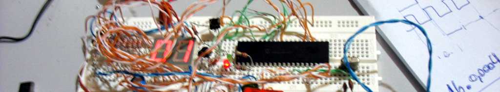
I implement this debounce using PIC Assembler, and the code are inside a huge amount of other things.
Below a quickly C version build . I think it can work without major changes.
Better would be change it to work like a function.
Also, I am using two IF inside each state change due I don't know how char will suffer with negative numbers.

///////////////////////////
// Hernandi Krammes - its me - chico
// 10-14-2010 - use with care! 

#DEFINE HIGH 8    // 8 states between changes 8*5ms = 40ms

char keyA_state;
char keyA;    // 0-1 - need just a bit - use whatever you want

ISR(){    // Interrupt Service Routine

          //   for me at 5ms or anything else

    // key debounce
    char tmp;    // just to hold the state of key
    tmp = getPin(pinA);

   // Pls, use a comparation that recognize the right pin state

   // I think that an LOGICAL AND should be a better approach
   // Let me say, bit 2 is the desired PIN
   // so the PINFILTER should be 'b00000010'
   // and the result will be 0 or 1 and the
   // state machine will work nice
   // Thanks to underwood from german that warm me
   // that the code seens to not work
   // I think that is because this
   // Beyond, code shoud work with any microcontroller
   // PIC, Atmel(AVR), etc
   if (!(tmp AND PINFILTER)){ //old mode deprec. (tmp == 0)
        if(keyA_state == 0) keyA = 0;
        else keyA_state--;
        if(keyA_state == 0) keyA = 0; 
    }else{  // tmp = 1
        if(keyA_state == HIGH) keyA = 1;
        else keyA_state++;
        if(keyA_state == HIGH) keyA = 1;
    }
    // ready! the rest int code goes here
}
// There is it. I hope that this could help someone!

Let your comment.

Friday, September 24, 2010

Plotter/Engraver part N

Finaly, the fisrt picture of my Plotter/Future Engraver.
Some considerations about builting with MDF.
As Zoltar say to me, I shouldn't had been use MDF. It is a little bit bad.
Also, I am using just one traction axis for the base, that cause to much leisure on edges of mechanics.
Also, IGUS is to much imprecise. But it work for fun!
I am using old epson drivers and Rima/Emilia motors, that work natively on 200 steps/rev and with microstep now are working with 800 steps.
As say on last post, a Windows software control everything.
The MICROCHIP receive the commands and execute; It make the Glue between all parts.
I chose to use a SERVOMOTOR to control Z axis now. PIC control it! Very tigtht due time limitations, but works.
Microchip have poor stuction set, even that it is fast.
AVR I think may work MUCH better, because the program speed lots of instruction ADDing with carry on Microchip, where with ATMEL AVR there is a instruction that ADD with carry in normal way.
Well, for now, just this. Tomorrow I post a more.
Today the control board (with LB1946) used to play music and make the first tests, BURN due a accidental short circuit.
Now I am fixing with other and older DRIVER CHIP (Aleggro A2919LBS) and ajusting the program to work with this new architecture.
It's a great achievement to use old parts for new and nice things.


Bellow the picture of the hardware already build! Little bit messy, sorry.

Tuesday, August 31, 2010

Plotter/Engraver

The first test with the plotter/engraver have just been done!
Next days, few pictures and videos of project!

Saturday, February 20, 2010

Twitter lixo

Mudando um pouco o foco das postagens...
Esse video postado pelo crash_computer é sem duvida engraçado.
Replico ele aqui. Minha visão é igualmente a dele. Twitter suck.

Changing a little bit the post, this video linked by crash-computer is really fun.
I repost it here. My opinion about is the same! Twitter suck.

Saturday, February 13, 2010

Nova versao do engraver/CNC - New engraver version

Abaixo a imagem da nova versao do engraver.
Como bonus de utilizar uma ferramenta de desenho CAD, é possivel avaliar diversos problemas antes de realmente colocar a mão na massa.
Ainda, é possivel pensar melhor em como fazer as coisas com poucos recursos, otimizando para reduzir o trabalho final!
Acredito que o projeto atual está muito mais proxima da versao final.
A mesa sabe foi colocada "dentro" do eixo X, assim facilitando o suporte do carro maior através das guias IGUS colocadas nas laterais internas do carro.
Consegui tambem uma chapa de aluminio de 3.6mm para fazer alguns detalhes de suporte.

Utilizarei no projeto as seguintes guias IGUS:
DryLin® W carrinho, montado
  • WW-10-40-10 - guia de 50cm
  • WW-10-40-15 - guia de 60cm
Tambem seram utilizados mancais da Igus.
Esses produtos sairam por aproximadamente 500R$ em 2009.

Wednesday, February 10, 2010

Programa para desenhos modo Plotter

O programa para efetuar desenhos no modo plotter está em estagio avançado.
Desenvolvido em DialogBox para Windows com Visual C 6. Em breve converterei o mesmo para SDI, permitindo assim mais facilidade de trabalho. Estou utilizando fortemente C++ orientado a objetos, o que vem facilitando muito o trabalho. Tambem o MFC da Microsoft, que auxilia bastante e evita muitos contratempos com programação Windows.
 Atualmente estou utilizando uma velha Epson SC 1500 como base para testes dos sistemas do PIC e do programa Windows.
Logo estarei postando um video do sistema em funcionamento...

English Version:
The program to draw over the test plotter is on advance stage.
It are being develop with Visual C with DialogBox mode. Soon as possible a will convert it to SDI interface, to allow more flexibility and better visual. Using MFC to abstract the huge complexety of Windows programming.
Actualy using as hardware for testing purpose of PIC and Windows programns a old Epson SC 1500 mechanim.
Soon as possible I will be posting a video of the system working!


Print do programa para gerenciar o plotter. Ele se encarrega de enviar as linhas a serem desenhadas via serial ao PIC. Este cuida de efetuar a interpolação na velocidade desejada. Tambem mantem suporte basico a teclas de entrada como botão de OnLine e setas para movimentar os eixos!

Screen of program to manage the plotter.  It manage the source image to be draw by the PIC. The data is send over serial conection. The PIC take care of interpolation process is desired speed.
Also there are basic suport to input buttons like OnLine and direction buttons for load purposes!

Saturday, January 23, 2010

New song - Hungarian Rhapsody No. 2 - on step motor

We proud presents to you... Hungarian Rhapsody No. 2 played by stepper motor

Details:
48 steps - 4 microsteps
song played 2 octave high
single tempo for all track - the tempo has not been found inside MIDI.
However the players get right?!
7Khz Max frequency.. but stepper dont work direcly on this speed
- need sinuodal rise of speed. need work on this yet.


Tuesday, January 19, 2010

The hardware to generate sound.

Here the pic of hardware to suport sound generation.


 Too a screenshort of progream that control all.


 And here other song played by steppers' motors!

Pachelbel's Canon
The motors are running in 4 microsteps. But the right one are with bad noise.
Aslso the song are being played 3 octaves high, for better sound.


Monday, January 18, 2010

First Test in speed control for stepper

I end the PIC program to control speed and a Windows interface to control and test the PIC program.
Soon as possible i will post the block diagram of PIC software.
Bellow a video of singer steppers made by my.
It are playing BigCity.mid song in 2 voices!
The bushless are better to make noise.
Using 2 motors for old Epson printers.
Using the driver from board of one old Epson to control both motors. Too using the power supply, to supply 5V and 42V.
But PIC are controlling the motors.
The pic receive the commands over serial, from windows, in XYZ and LENGHT over time numbers.
So PIC control the step generation.
It's like the "Dueling Steppers", found on Youtube.
Enjoy!

Saturday, January 02, 2010

CNC SPEED Control

Since then we talk about accurate control multiple axis, we should remember that all axis speed get together based in pitagoras equation in simple orthogonal system (XYZ system). Based in simple 3 axis in orthogonal system (90°), each one running at 30mm/sec, the final speed can be calculed as SRQT(X^2+Y^2+Z^2) and must be aprox. 51,96 mm/s. That is just a exemple... but show that the final speed must be corrected in all axis in a sincronized way.
So if you control just indidually each axis, you dont get the right speed.

Based in this "problem" I made a "algoritm" to control the final speed for use with simple microcontroller.
I think that was solved by many commercial and free softwares already, but for my CNC, i appreciate implement it.
It generate 4 simple data that can be user by any microcontroller easyly with fixed math to controll accurately the speed of all axis for each line it process, getting always the right speed for final movement as desired, and based in clock that microcontroller will drive the motors (INT clock!). I implement the initial idea using excel; so as I align and clean everything in the file, I will put the excel file here with formulas.
By the moment I just show to you the most precisous part of project.
The schematic of all thing! Its a huge image(3000 x 1500 px), so be patient!


I blend portuguese and english, but all we are smart enough to get the right understanding.
Basically, I get all the XYZ real data, and process it to get the the accurate speed and shift values. Green boxes represent the input data, by user or by stream of line to be processed. Blue boxes represents the simple data to be send to microcontroller. As inexpensive microncontroller work nice with fixed math, and there are lots of code for fixed math, its much more easy to use it, I make everithing thinking in that way. The output of algoritm use a fixed floating point for control each axis, based in microcontroller interrupt CLOCK, and with a Npassos amount of steps to be run by clock. I make the reverse calculus in Excel, based in rounds that pic will execute, to see if everything runs nice. The final data show great, with little error. Since we use more that 4 decimal places behind the dot. (0.xxxx)
The system to admits that we can use variable size step motors and variable speed reduction for each axis (like the screews of diferrent kinds). The final speed, given right values, will be garanted.
I dont make a analisys to get the MAX final speed supported by the system.
BUT have in mind, the X || Y || Z OUTPUT DATA must never be great that ONE; if this happen, some are wrong...
the desired speed are to HIGH for the choice CLOCK; you must put higher CLOCK (but you can get problems with frequency suported by your steep motors, it can hung); or you have to use a more fast XYZ transfer axis(screew); or fast step motor with little steps per revolution. It's your choice.
By now are too hot here, and I have to lunch. Soon as possible I will post the remaind of project.